|
|
Post by arcadetv on Feb 9, 2015 7:25:14 GMT -8
Hi guys, I entered the Arduino world 2 weeks ago so please excuse me if my questions seem dumb.
I work as a webdeveloper and I'm totally into electronics and golden-age-videogame systems as a hobby. Now I'm building arduino-driven switchbox for 15kHz-RGB-capable consoles.
It all works very well, I'm having a good time with coding, the hardware and pcb-layouting. I'm using a small OLED I2C display for my visual-output, but i'd love a better presentation for the user.
While searching for embedded GPU's for arduino I found the GD2 with its FT800 to be just what I was looking for.
Having no experience with either GD1 or 2 I do have some questions to evaluate my options for my next decision...
Looking at the GD1's specs I think "why is this 32kHz/VGA only... would have been so nice if it would support 15kHz RGB like many videogame systems do."
I was hoping for being able to present my user-menu directly on the TV (European RGB-capable Scart, 50Hz/60Hz hor. refresh doesn't matter)
Is there a way to run the GD1 in 15kHz? (I guess the GD2 would be out of question, would it??)
So, if creating a 15kHz-video-signal is not an option, I will have to include a screen into my project-box...
A touchscreen would be overkill for this, honestly, so does anybody know of a cheap compatible screen (without touch) for the GD2/FT800?
|
|
|
|
Post by jamesbowman on Feb 9, 2015 21:28:06 GMT -8
|
|
|
|
Post by arcadetv on Feb 10, 2015 2:44:17 GMT -8
I bought a GD2 at the german shop that you linked to on the main page so I get to play around with it soon.
Also I found the PSP-display board at AtomSoft's site, I guess I'll give it a try.
James, can I do anything to make you look into the GD1's fpga code and make a 15kHz-Version? ^^
No need to change the hardware, only the timing in the verilog code.
This would be like "Uzebox" (http://www.hwhardsoft.de/english/projects/euzebox/) but for Arduino...
Anyways, thanks!
|
|
|
|
Post by arcadetv on Feb 26, 2015 2:44:10 GMT -8
I'm still wrapping up my setup...
There are some quirks while my GD2 is connected to my Arduino MEGA2560 due to long jumper-cables.
I also got the screen from HOTMCU that James recommended.
Could you please explain what needs to be changed in order to get this working with the GD2 library?
Thanks!
|
|
|
|
Post by arcadetv on Mar 2, 2015 4:06:57 GMT -8
What are the simple changes related to? Wiring or library? Thanks! |
|
|
|
Post by jamesbowman on Mar 2, 2015 11:37:39 GMT -8
After from making the SPI hookup - if you change this line:
github.com/jamesbowman/gd2-lib/blob/master/GD2.cpp#L8
in the library so that PROTO is 0, and on the next line set STORAGE to 0, then it should work fine with 3rd party FT800 boards like this - apart from not having the SDcard/accelerometer function.
|
|
|
|
Post by arcadetv on Feb 26, 2016 8:05:15 GMT -8
It's been a while since I last visited.. I could reaaalllyyy use a helping hand... I have the HY43B/HY50B here and it works with the arduino-library from ftdi. I can't get it to work with the gd2-lib  I suspect it may be related to wiring... I've pulled the latest files from github and changed lines 15 and 16: #define BOARD BOARD_FTDI_80x // board, from above #define STORAGE 0 // Want SD storage? My current wiring on the UNO is: Adapter ↔ Arduino UNO
5V ↔ 5V GND ↔ GND SCK ↔ D13 MISO ↔ D12 MOSI ↔ D11 CS ↔ D8 INT ↔ D2 PD ↔ D4 (I've set the pin HIGH in my test-code, since it's buffered via a LS125 on the TFT-Board, on GD2 it's perm. connected to 3.3V) The wiring that worked for FTDI's library was: Adapter ↔ Arduino UNO 5V ↔ 5V GND ↔ GND SCK ↔ D13 MISO ↔ D12 MOSI ↔ D11 INT ↔ D10 CS ↔ D9 PD ↔ D4 As for curing curiosity.. the screen looks like this from behind: 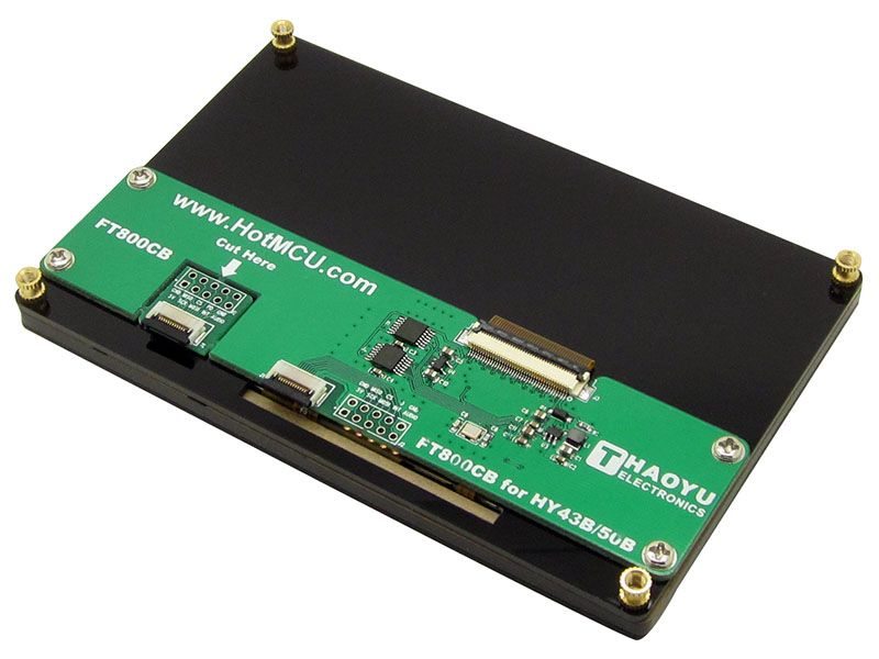 ![]() |
|
diesel
Junior Member

Posts: 22 
|
Post by diesel on Feb 27, 2016 18:34:52 GMT -8
Try this
void Setup(){
GD.wr(REG_SWIZZLE, 0);
I am interested to see the screen quality, those are just $35.00 bezel and all.
|
|
|
|
Post by arcadetv on Feb 29, 2016 1:42:17 GMT -8
Inverting the order of the RGB-Bits by calling REG_SWIZZLE did not work Still getting a white screen. The quality of the screen is very fair, the only thing that could be better is the viewing-angle. |
|
|
|
Post by jamesbowman on Mar 2, 2016 6:32:33 GMT -8
|
|
|
|
Post by lightcalamar on Jun 21, 2016 14:58:25 GMT -8
|
|
|
|
Post by jamesbowman on Jun 22, 2016 8:00:20 GMT -8
Nice! Is it possible to connect PD_N to a Arduino digital pin (e.g. pin 6), and then the Arduino can reset it like this:
pinMode(6, OUTPUT);     // pull pin 6 (FT800 PD_N) low
digitalWrite(6, LOW);
delay(5);               // hold low for 5 ms
pinMode(6, INPUT);      // release

GD.begin();
because then there are no extra components?
|
|
|
|
Post by lightcalamar on Jun 23, 2016 13:56:28 GMT -8
Thanks James
With you code not work.
After consulting datasheet IC FT800 only POR (Por On Reset (Page 49)) 5ms, else runnig, this working:
#define PDNPin 8
// INTO SETUP
pinMode(PDNPin, OUTPUT);
digitalWrite(PDNPin, HIGH);
delay(20);
digitalWrite(PDNPin, LOW);
delay(20);
digitalWrite(PDNPin, HIGH);
delay(20);
Best regard
|
|
|
|
Post by tofumax on Mar 19, 2017 11:54:48 GMT -8
I stil not find e solution for my problem
mega 2560+ Ft811 gon frozen
could you send mi a GD2-3 Library which works witf mega 2560
and arduino softwere you use
|
|
|
|
Post by lightcalamar on Mar 20, 2017 0:26:36 GMT -8
Put your library, then put the connection diagram and I can help you
Regards
|
|


 I suspect it may be related to wiring...


